Adjustable Legs
An Introduction to Free-mo, Part 3: Building the Legs and Leg Pockets for Your Platform
By Mike Tietz and Jerry Barsness with technical assistance from Frank Wilhelm
One of the things you will have to take into account before you start to cut material for the legs is how it will affect the overall height of the platform and it’srail height from the floor. The Free-mo nominal and minimum height of the railhead, at the end plate, is 50 inches from the floor. However, at a lot of non-Free-mo meets the rail height is 42 inches from the floor. The lower height allows for better viewing by the public and is referred to as the “Show Height.” Therefore
module legs should be adjustable in length to allow for the international 50-inch rail height as well as the optional 42-inch rail height. Alternatively, two sets of legs are acceptable. So the two things to take into account before you set the length of your leg set are: Where will it mount to your platform and what size and type of adjusters will you use on them?
You will also need to decide on the type of legs you are going to use on your module. Are you going to build an adjustable leg set, a folding leg set, or two different sets of non-adjustable leg sets? It is all up to you and there are many ways to construct them as long as you build them to the standards of height and floor protection.
While there are many ways and types of leg sets that have been used, what follows is but one way of building them. During the construction of the end plates and some modules from the 3/4 inch birch Plywood we found that we had a lot of pieces of 3/4 inch birch left over that seemed unusable for any of our other components. We decided to use some of these strips for our leg sets and the leg pockets. Avoid dimensional pine lumber for your leg sets. It has a tendency to warp with age, and it varies in size from retailer to retailer making the fit into the leg pocket difficult.
We made our leg pockets out of the same 3/4 inch material. Now you will need the leg pockets to be at least 5 inches deep and you will need four of them. So you will need at least 20 inches for each of the four sides of material to make your leg pockets.
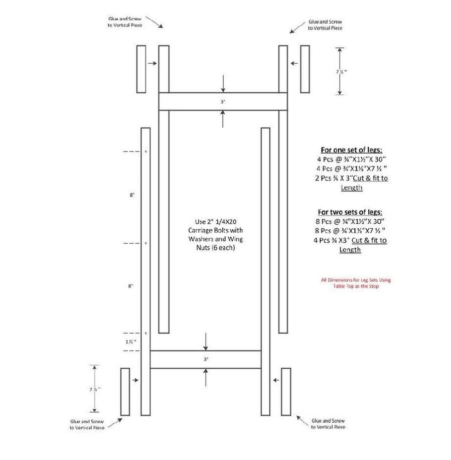
First cut some strips 3 inches wide. These can be one length at 40 inches long or two pieces at 20 inches but none less than 5 inches long. Then cut the same amount of strips 1-1/2” wide. Again either 40 inches long or use remnant pieces as above.
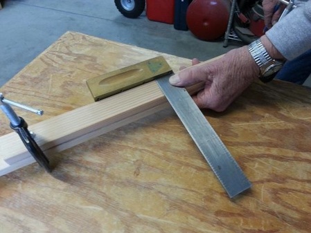
As a guide for the assembly of the leg pockets, we first cut a piece of lumber at1-1/2 inches on all four sides to assure
that our pocket would properly receive the legs. We then placed one strip of the 3 inch and one strip of the 1-1/2 inch together with a thin piece of card stock as a spacer. Add a thin amount of wood glue and nail together holding both pieces firm to the form. Do the same for the other side.
that our pocket would properly receive the legs. We then placed one strip of the 3 inch and one strip of the 1-1/2 inch together with a thin piece of card stock as a spacer. Add a thin amount of wood glue and nail together holding both pieces firm to the form. Do the same for the other side.
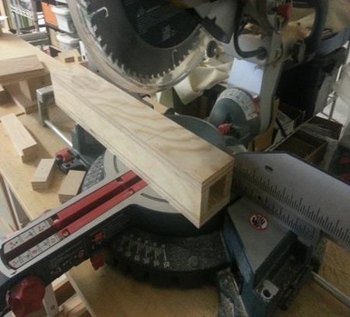
Once you have your pocket assembly done, or the pieces, cut them to 5 inches in length taking care to avoid cutting through any nails.
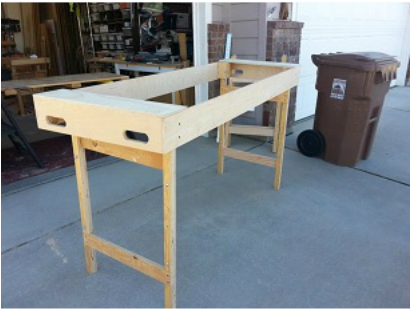
Now your pockets are ready to install on your module!
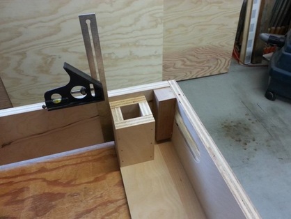
Mount them with the outer 3 inch side of the pocket against the module side. This gives you a good flat surface against the frame. Square it up using a square and clamp into place.
Use wood screws to attach to the module frame taking care not to protrude into the leg pocket and interfering with the leg when it is installed.
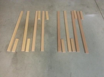
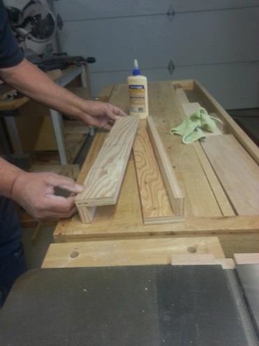
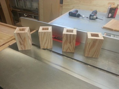
The picture at left shows the leg components cut and laid out that will be needed to assemble the two sets of legs for your module platform.
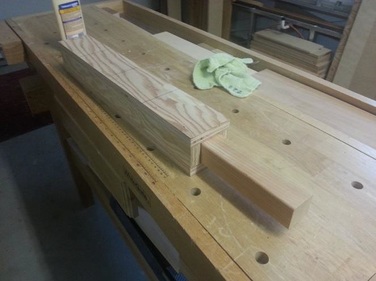
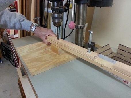
In the next picture we are gluing and installing the 7-1/2 inch piece to the bottom of each leg component. When there are many to do it is helpful to set up a jig to help with your production. A little wood glue and a couple of nails will hold it all together for you.
In the next picture we are gluing and installing the 7-1/2 inch piece to the bottom of each leg component. When there are many to do it is helpful to set up a jig to help with your production. A little wood glue and a couple of nails will hold it all together for you.
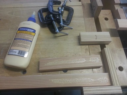
You will need some clamps and wood glue at this stage.
Here we are using some of the strips that we cut per our drawing. They are 3/4 inch Birch cut to 30 inches long with the 7-1/2 inch piece glued and nailed at the end. You will need two sets of these for each side of the leg set.
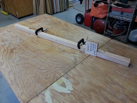
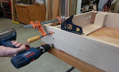
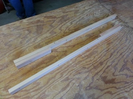
Next set the two pieces together and set a 3 inch wide spacer where the cross member will be installed. Clamp it together. Mark your leg set at the three spots per the drawing where you will need to drill for your adjustable carriage bolts to be installed.
Now mark the holes for drilling for the adjustments of the 42 and 50 inch positions.
Keeping it all clamped together you can drill the holes. Use a 9/32 inch drill bit to accommodate the 1/4 inch carriage bolt. Install the carriage bolts, washers, and wing nuts.
Your leg is now complete and should fit into the leg pocket smoothly.
Just a note: You can also sand a slight bevel on all four sides of the leg that enters the leg pocket for added ease of installation.
By installing the bolts in their lower positions, a nominal track height of 42 inches is achieved. However, when installing the bolts in their higher positions, a nominal track height of 50 inches is achieved. Each leg is fitted with a screw-type adjustable foot in a T-nut for adjustment to account for uneven flooring surfaces. If when you have completed your leg sets and find that your overall rail height is too tall, you can always cut off a little to bring them into the proper
table height.
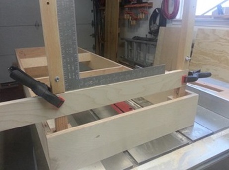
Install the completed leg into the leg pocket. Set the cross brace piece across both legs and check using a square, true each leg and clamp it all down. Mark the length of the cross brace, remove and cut.
Now reinstall the cross brace, true it all up and screw it together on both sides. Add the other cross brace and check for trueness. Clamp it into position. Mark and cut the other cross brace to the legs and screw it into position. Now do the same for the other side.
Now reinstall the cross brace, true it all up and screw it together on both sides. Add the other cross brace and check for trueness. Clamp it into position. Mark and cut the other cross brace to the legs and screw it into position. Now do the same for the other side.
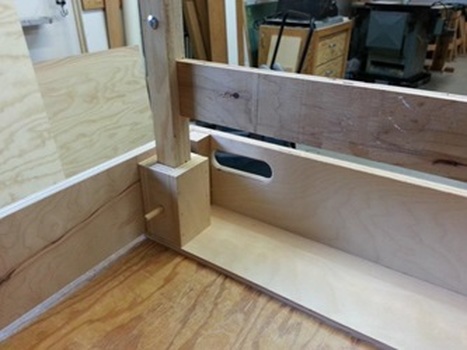
It can all be used as is now or you can drill a 1/4 or 3/8 inch hole through the leg pocket and into the leg assemble for a piece of dowel to hold the legs in place while you set your module upright. You can use whatever size dowel you want and tapper one end of the dowel pin for ease of installation into the leg.
Free-mo standards address two other aspects of leg construction: First, S2.9 states that “Legs shall have continuous adjustment of plus or minus 1 inch (screw type foot).” The purpose of this standard is to allow for adjacent modules to be true and level when set up on an uneven floor. Second, S2.10 states that “The bottoms of the legs shall have rubber tip or equivalent floor protection.” Although any setups will be on concrete or some other durable surface, this standard ensures that other surfaces will be protected.
Free-mo standards address two other aspects of leg construction: First, S2.9 states that “Legs shall have continuous adjustment of plus or minus 1 inch (screw type foot).” The purpose of this standard is to allow for adjacent modules to be true and level when set up on an uneven floor. Second, S2.10 states that “The bottoms of the legs shall have rubber tip or equivalent floor protection.” Although any setups will be on concrete or some other durable surface, this standard ensures that other surfaces will be protected.
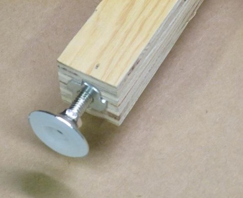
As mentioned above, a screw-type adjustable foot in a T-nut for adjustment can easily be installed to account for uneven flooring surfaces. There are several types of feet that can be used with this arrangement.
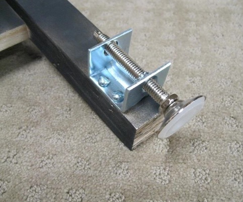
An alternative is adjustable brackets that are attached to the side of each leg. An advantage of this style of adjuster is that you can quickly and easily move the legs up and down using a screwdriver.